LOW FREQUENCY OR LINE FREQUENCY CURRENT TRANSFORMER APPLICATION NOTES.
This application note on current transformer principle and application is intentionally written in its most simplest and basic format so that everyone from engineers to technicians to sales persons can understand how a basic transformer and in particular, a current transformer works.
TURNS RATIOS AND VOLTAGE RATIOS
The starting point is the understanding of turn ratio, voltage ratio, and current ratio. Transformer is a passive device and its only purpose is to step up or step down an applied AC voltage to its input with the resulting transformed AC voltage at its output. This is accomplished by the transformer’s input to output turns ratio.
Technically, the total voltage induced into the secondary winding of a transformer is determined by the ratio of the number of turns ( i.e. turn ratio) in the primary to the number of turns in the secondary, and by the amount of voltage applied to the primary.
So, if a transformer has 10 turns of wire in the primary windings and a single turn of wire in the secondary winding, then the turn ratio is 10:1.
This means that if the voltage applied to the primary winding is 20 volts AC, each turn in the primary will have an induced voltage of approximately 2 volts (20 volts divide by 10 turns). i.e the volts per turn is 2.
This “volts per turn” is same for both primary and secondary windings, assuming an ideal transformer.
With a 10:1 turn ratio, the secondary will have 2 volts. Another way of looking at this is as follows. Since there is only 1 turn in the secondary, each turn is 2 volts AC.
The relationship between the number of turns in each winding and the voltage across each winding is expressed below.
Note the equation shows that the ratio of secondary voltage to primary voltage is equal to the ratio of secondary turns to primary turns.
EFFECT OF A LOAD
When a load device is connected across the secondary winding of a transformer, current flows through the secondary and the load. The magnetic field produced by the current in the secondary interacts with the magnetic field produced by the current in the primary. This interaction results from the mutual inductance between the primary and secondary windings.
The total flux in the core of the transformer is common to both the primary and secondary windings. It is also the means by which energy is transferred from the primary winding to the secondary winding. Since this flux links both windings, it is called MUTUAL FLUX. The inductance which produces this flux is also common to both windings and is called mutual inductance.
TURNS RATIOS AND CURRENT RATIOS
As the current flows into the primary windings, this current produces the flux lines in the transformer core. This flux lines is proportional to the magnetizing force, also called NI (or ampere-turn) of the primary and secondary windings. This NI is a measure of magneto motive force. This magneto motive force is created by one ampere of current flowing in a coil of one turn. The NI in both the primary and secondary windings is the same.
Therefore:
Note that the current ratio is the inverse of the turn ratio and the voltage ratio. For example, a transformer with a 8:1 turn ratio between the primary and secondary windings, a 10 amps applied to its primary windings will result in a 10x8 = 80 amps of current in the secondary windings.
If a transformer has a 1:50 turn ratio between the primary and secondary windings, a 10 amps applied to its primary winding will result in 10/50 = 0.2 amps of current in the secondary winding.
LOW FREQUENCY AND SMPS CURRENT TRANSFORMER
A current transformer is a transformer with a single primary winding, and usually hundred or thousand of secondary windings. Its purpose is to measure the primary current flowing through the primary wire or cable. This determination of the amount of AC current is done by measuring the voltage across the burden or load resistor connected to the secondary outputs. There are many applications where an engineer would want to measure the amount of current flowing in a wire or cable.
This section covers the 50 Hz to 200 Hz types of current transformer application.
The data sheets in PDF from Coil Winding Specialist Inc website contains the basic information needed to do a current transformer design.
The turn ratio between primary to secondary is usually 1:1000 or 1:2500, but custom turn ratios are available. Please download a sample pdf file to see the turn ratios, suggested burden resistor and other parameters.
As an example, the CT-000A has a turn ratio of 1:1000. The rated primary current is 25 Amps of a 50Hz to 120 Hz power line.
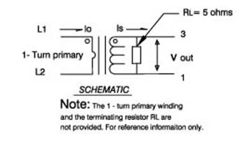
From the schematic of the current transformer above, if the primary current “Io” is 25 amps, the secondary current “Is” would be 25/1000 = 0.025 mA. The load or burden resistor “RL” connected across the secondary terminals 1 and 3 is 5 ohms. So the voltage across RL is 0.025 x 5 = 0.125 volts.
If only 10 Amps of primary current is flowing through the cable, the voltage across RL would be 0.010 x 5 = 0.05 volts.
Since voltages are very easy to detect and measure, a graph can be drawn to show the voltage across RL versus the primary current. In the above case, a 0.05V is equivalent to 10 amps on the primary and a 0.125V is equivalent to a 25 amps on the primary cable.
After the burden resistor (RL), a simple RC filter is usually needed to prevent high freqency noise inteference when detecting the voltage across RL. To do this, a small capacitor (C) can be connected in parallel to the RL, followed by a small resistor (R) forming the RC filter network.
The accuracy class or the linearity of a current transformer tells how accurate a current transformer is. In other words, how accurate is the actual primary current in proportion to the measured voltage across RL. An accuracy class of 1% means there is a 1% error. So, in the above example, a 0.125V measurement of the voltage across RL would mean the primary current could be 25 Amps + - 1%.
Coil Winding Specialist Inc ("CWS") current transformers have error class rating from 0.5% to 5%, depending on the types of core materials used and the DC resistance of the secondary windings. In some application, there are DC current on the power line and the AC current is riding on top on the DC current. To measure these AC current, the CWS' IEC60044-1 Compliant DC-Tolerant (50-200Hz) Current Transformer Encapsulated CT100 Series can be used to measure the AC current.
Phase error
Another error in the current transformer is the phase error. This error is important in some metering application.
Phase error is a measure of how accurate the phase of the primary current waveform matches the secondary current waveform. It is also called the phase angle error between primary current “Io” and secondary current “Is”. This error is due to the magnetization current of the current transformer and the burden resistor. The smaller the burden resistor value, the smaller will be this phase angle error. This is why burden resistors are usually small values. Coil Winding Specialist Inc’s (CWS) data sheet shows the phase error of various models based on the recommended burden resistor value.
CWS specializes in custom designs for Current Transformers and Ground Fault Interruptors for any specific application using amorphous or nanocrystailline cores. Please contact sales@coilws.com for comments or additional information or application assistance.